Using the RPLIDAR A1 on the MIT Racecar
Using the A1 lidar with ROS is easy! RoboPeak provides a ROS driver that worked out-of-the-box, and I only made slight modifications to the Racecar code. Here’s what I did.
The RPLIDAR A1
The MIT Racecar normally has a Hokuyo UST-10LX lidar, but I decided to save $1,000 and use an RPLIDAR A1 instead. The A1 has good enough accuracy for me, but if I ever want to upgrade I can get an A2 or A3 for a couple hundred dollars more.
Connecting to the A1
The A1 typically appears as /dev/ttyUSB0, but I gave it a more readable, consistent name using udev rules. By adding the following line to my rules file (any rules file will work, but I have one for racecar-specific rules), the A1 will always appear as /dev/rplidar
# etc/udev/rules.d/10-racecar.rules
KERNEL=="ttyUSB*", ATTRS{idVendor}=="10c4", ATTRS{idProduct}=="ea60", MODE:="0777", SYMLINK+="rplidar"
I found the vendor and product id via lsusb
ROS Package
The A1 driver node connects to the lidar and converts its data into LaserScan messages. A Hokuyo will publish the same LaserScan message, just with more data points included, so any navigation system using a lidar will work with either.
First, I cloned the ROS package to my catkin workspace
cd ~/racecar_ws/src
git clone https://github.com/robopeak/rplidar_ros
and added the rplidar dependencies to my CMakeLists.txt and package.xml files.
# CMakeLists.txt
catkin_package(
    CATKIN_DEPENDS
    rplidar
    ...

# package.xml
rplidar
Then I updated the racecar launch files to start the RPLIDAR node instead of the Hokuyo node. I turned on angle compensation to reduce shaking, and it works really well!
# sensors.launch
I also told the node to use the new symlink I created earlier.
# sensors.yaml
laser_node:
  serial_port: /dev/rplidar
Updating TF data
In order to build a map of an environment, a mapping package like gmapping needs to know the position of the lidar relative to the racecar base link. ROS uses a handy library called tf2 to publish static coordinate frame transform data like this.
The default racecar project already defines the default coordinate transforms between the base_link and laser frames.. Since the A1 doesn’t fit in the existing lidar slot, I had to moveit up 2cm and back 2cm. The exact measurements will depend on your setup.
# static_transforms.launch.xml
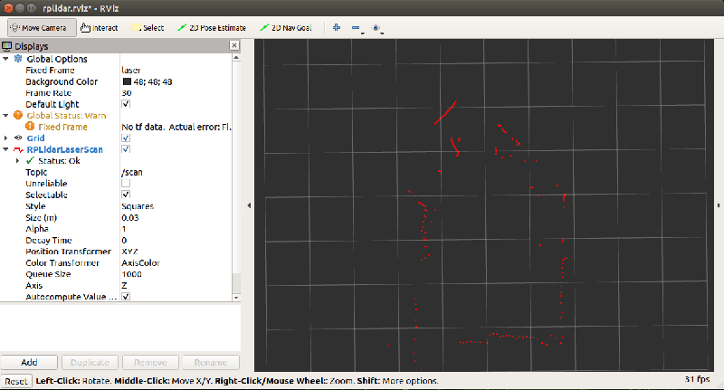
Seeing lidar data
The A1 driver includes a handy launch file to visualize the lidar data. This command starts the lidar and shows its scan data in rviz.
roslaunch rplidar_ros view_rplidar.launch
Now that the lidar works in teleop mode, the next step is to use `gmapping` to build a map of my apartment. See you soon!