Coilgun V2
Some History
Making a proper coilgun has been a dream of mine since high school, and senior year of college I was fortunate to receive a small grant to build an exhibit for the U of M’s CSE expo, an event to show fun science projects to middle school students. I thought that a sci-fi weapon would be the perfect thing to get kids interested in science.
The parts that I ordered online came about two days before the actual expo, but I managed to slap something together for the kids. Here’s a video of my original coilgun.
What a disappointment. Not even the middle-schoolers were impressed! The technology behind it was sound, but my dream of making a sweet coilgun would take some more work. Eventually, my coilgun became a bit of a running joke in Mad Scientists Club (the engineering club I co-founded), but now I’m proud to report that V2 is up and running.
Coilgun Basics
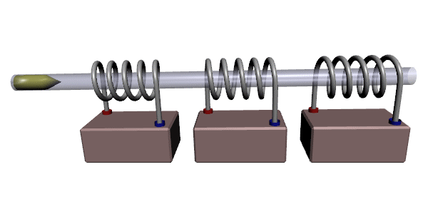
A coilgun is a type of electromagnetic accelerator that creates a powerful magnetic field through a coil to accelerate a projectile. Before you ask, coilguns are not the same as railguns. Railguns operate on a different electromagnetic principle and use rails instead of coils :D.
Anyway, to power a coilgun, electrical energy is stored in capacitors, which are the large blue cylinders in the video above. Once the capacitors are charged, their energy is released through a coil, and the resulting current produces a very strong magnetic field. This fields attracts a ferromagnetic projectile (a nail) and pulls it towards the center of the coil. The magnetic field lasts for only a few milliseconds, so by the time the projectile is in the center, it continues shooting out the other side. If the magnetic fields lasts too long, it will simply hold the projectile in the coil, and no children will be impressed.
Now let’s take a look at how I improved my old design!
Coilgun V2 Goals
For my second coilgun, I had few basic goals:
- Shoot faster
- Have a safer enclosure
- Take up less space on my shelf
- Use all eight of my capacitors
There are plenty of great coilgun resources online, so I’m not going to make this into a perfect step by step guide. If you’re interested in building a coilgun yourself, I recommend the following:
- Barry’s Coilgun Design Site: Easily the best coilgun resource I’ve found. The simulators were particularly helpful, and I found solutions each time I messed up and burned up a component.
- Delta-V Engineering: This guy made one of the coolest-looking coilguns around (it was in Dark Knight Rises!), and I used his ideas for the SCR and charging circuit.
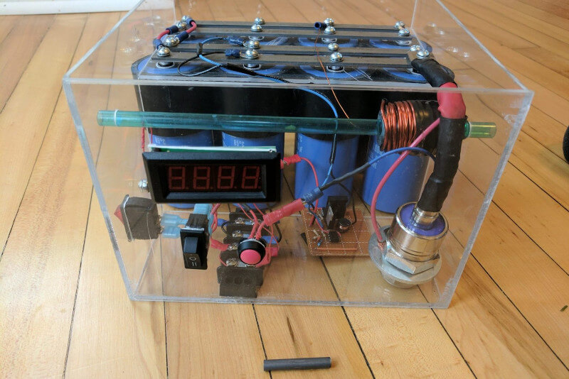
Components
- Capacitors: 8 x 1800μF 450V electrolytic capacitors
- Charging Circuit: 15W boost converter, limited to 200V.
- SCR: Used the KP200A, which can handle an momentary current of 2,000A. Bought it on Amazon.
- Coil: Around 50 turns of 16 AWG magnet wire.
- Projectile: 1/4″ iron rod.
- Case: 1/8″ Clear acrylic. I recommend a solvent-based adhesive specifically designed for acrylic to hold everything together.
- Barrel: Plastic party straw from Target.
Struggles
My main issue with V2 was keeping it from frying my charging circuit when firing at a high voltage. The first day I successfully fired the coilgun, it burned out the mosfet in the charging circuit. While I waited for a new one to arrive, I realized that I hadn’t heeded Barry’s warning about damping resistors.
Coilguns create a circuit between a bank of conductors, an inductor (coil), and a small amount of internal resistance. Electrical engineering students will recognize this as the well-known and fascinating RLC Circuit. When an RLC circuit with low resistance discharges, its voltage will oscillate because its components are all out of phase with one another. This oscillation can damage electrolytic capacitors, and in my case it destroyed my mosfet.
The chart below shows an graph of voltage in an RLC circuit.
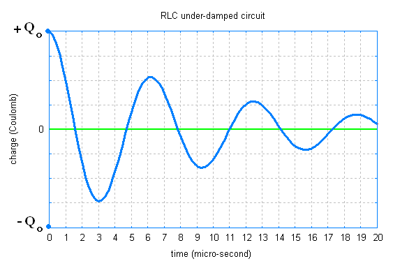
To protect my capacitors and charging circuit, I put a protective diode over the coil. This diode allows the negative voltage to discharge safely, and requires no changes to the existing circuit. It worked very well, up until about 130 volts, when this happened.
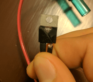
My protection diode wasn’t tough enough, and it exploded in a shower of sparks! I was wearing safety glasses at the time, so everything was fine, but my mosfet was broken again.
After I replaced the mosfet again, I decided to add a damping resistor instead of a protection diode. A damping resistor adds enough resistance to prevent the voltage oscillation from ever happening. For my coilgun, I calculated that I needed 0.12 Ohms of resistance, which equates to around 1.5 meters of 24 AWG copper wire. I added the extra copper wire around the coil (ignoring any added inductance), and I verified with an oscilloscope that the oscillation is gone!
Final Results
The new coilgun looks great! Here’s a video of it in action:
Let’s see if it met my initial goals:
- Shoot faster ✔️
- Have a safer enclosure ✔️
- Take up less space on my shelf ✔️ (technically has more volume, but the smaller footprint is great)
- Use all eight of my capacitors ✔️
Party time!